
Check the wiring to the throttle position sensor to make sure it is connected properly, that wires are insulated properly, and no wires are damaged.
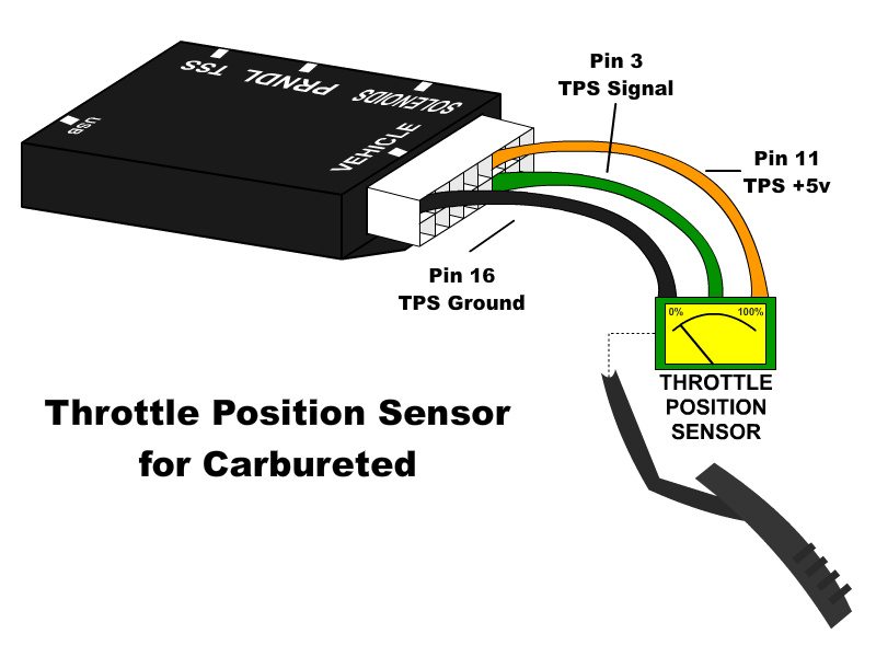
Ford has two different color codes for throttle position sensors and several different connectors and pin-outs. The early-style color code mostly matches the wiring of our harnesses: Black is ground and should be tapped into the black main ground wire from vehicle pin 16, orange is the 5 volt reference feed to the sensor, and green is the signal output from the sensor. Later Ford versions use a different color code where gray with a red stripe is ground and should be tapped into our black main ground wire from vehicle pin 16, brown with a white stripe is the 5 volt reference feed to the sensor and should be connected to our orange wire on vehicle pin 11, and gray with a white stripe is the signal output from the sensor, which connects to our green wire on vehicle pin 3. It is not safe to assume that the color code is correct if the plug came from an auto parts store or a different vehicle than the sensor.
| Ground Pin 16 Black |
+5v Reference Pin 11 Orange |
TPS Signal Output Pin 3 Green |
|
| US Shift Edelbrock TPS Kit (Harness Wires) | Black | Orange | Green |
| US Shift Edelbrock TPS Kit (Sensor Wires) | Yellow | Green | Red |
| RTD TPS Kit | Black (Terminal A) | Red (Terminal C) | White (Terminal B) | Holley TPS Kit | Black | Gray | Blue |
| Early Ford | Black | Orange | Green |
| Late Ford | Gray / Red | Brown / White | Gray / White |
| GM | Black | Gray | Blue |
Identifying the Terminals of an Unknown TPS
This is a procedure for identifying the correct terminal connections of any potentiometer-style throttle position sensor (almost all three-terminal TP sensors). A DVOM or analog Ohmmeter is required.
1. Set the meter to resistance mode and set it to a scale that can read up to 10K or 20K Ohms (if it is not auto-ranging). Keep in mind that "K" means thousands of Ohms, so 15K Ohms is the same as 15,000 Ohms.
2. Connect the meter to two pins at a time while operating the lever or cam of the TPS. Watch the meter while rotating the sensor. Check all three pairs of pins until you find a pair that does not change resistance when you rotate the sensor. The two pins that do not change resistance are the fixed ends of the resistance element (+5V and ground). The remaining pin that did change is known as the "wiper". It is the moving contact that slides along the resistance element to give the varying voltage. This is the output terminal of the sensor and should be connected to our green wire (Vehicle pin 3).
3. Next, with the sensor at the idle or closed throttle position, measure the resistance between the wiper (output) and each of the end terminals (the two whose resistance did not change in step 2) of the sensor. The end terminal with the lowest resistance to the wiper (at idle) is the ground terminal and should connect to the black main ground wire of the TCS (Vehicle pin 16). The terminal with the higher resistance to the wiper is the 5 volt reference input to the sensor and should connect to the orange wire (Vehicle pin 11) in our harness.
General Guidelines for setting up Throttle Position Sensors
The linkage to a throttle position sensor should use most of the rotating range of the throttle position sensor. This can be adjusted by changing the ratio of the linkage. Make sure that a small amount of the sensor's travel is being used at idle. You will want a TPS voltage at idle of at least 0.35 volts. This is done to allow the controller to detect problems with the TPS so that it can enter a "safe default" mode. For instance, if the sensor becomes disconnected or the linkage falls off, the TPS voltage will fall below the set idle threshold. If the TPS voltage goes below the idle threshold, the controller assumes that the TPS is bad and will switch to failsafe line pressure and default shift points. This is done to prevent damage to the transmission from low line pressure and will provide a safe "limp home" mode.