
With the ignition on and the PRNDL connector plugged into the controller,
use a volt meter to check the sensor signals.
Put the black probe to main ground, where the wire connects to the battery, and test each wire of the PRNDL connector with the red probe.
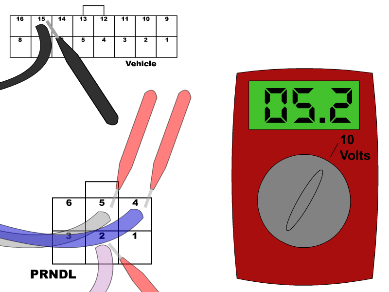
Go through each gear position and compare the voltages to the chart below.
GM transmission range positions and their acceptable voltages.
| Position | Pink Voltage | Dark Blue Voltage | Gray Voltage |
|---|---|---|---|
| P | 5 - 15 Volts | 0 - 0.8 Volts | 5 - 15 Volts |
| R | 0 - 0.8 Volts | 0 - 0.8 Volts | 5 - 15 Volts |
| N | 5 - 15 Volts | 0 - 0.8 Volts | 5 - 15 Volts |
| OD | 5 - 15 Volts | 0 - 0.8 Volts | 0 - 0.8 Volts |
| D | 5 - 15 Volts | 5 - 15 Volts | 0 - 0.8 Volts |
| 2 | 5 - 15 Volts | 5 - 15 Volts | 5 - 15 Volts |
| 1 | 0 - 0.8 Volts | 5 - 15 Volts | 5 - 15 Volts |